Beyond the Price Tag: The Value of Quality over Low-Cost Component Manufacturing

In today's fiercely competitive market, businesses are constantly seeking ways to optimize costs and improve profit margins. One common approach is to prioritize low-cost component manufacturing. While cost reduction is undeniably important, focusing solely on the price tag may not always be the best way to move forward. In this blog post, we will delve into the complexities of component manufacturing and explore why a balanced approach that emphasizes quality over low cost can lead to more sustainable and long-term success for businesses.


The Hidden Cost of Low-Quality Components:

Sourcing components at the lowest price may seem strategic, but it often comes with hidden costs. Low-quality components can lead to issues such as increased downtime, frequent breakdowns, and costly repairs or replacements. For Contract Manufacturers, these problems could even cause Production Line Down situations, which are costly affairs manufacturers want to avoid at all costs. These factors can significantly impact overall productivity and customer satisfaction, ultimately outweighing initial cost savings.


The Role of Reliability in Building Trust:

Industries where safety and reliability are paramount, like automotive, aerospace, or medical equipment, cannot overstate the value of quality components. Customers rely on products that perform consistently without fail. Investing in high-quality components builds trust with customers, enhancing a company's reputation, fostering long-lasting relationships, and encouraging repeat business. Recent Product Recalls across various industries could be partially attributed to component-level failures—often linked to extreme cost-cutting in component parts. While these costs might not be apparent during project budgeting, they significantly affect profitability.


Long-Term Cost Savings:

As mentioned earlier, low-cost components might offer immediate financial benefits, but investing in quality components leads to substantial long-term cost savings. Durable and reliable components reduce maintenance expenses, extend product lifespans, and decrease the need for frequent replacements. Enhanced product performance often translates into greater customer satisfaction and higher demand, positively impacting a company's bottom line. The correlation between procuring components of High Quality and Reliability is observable, as they both influence the product owner's reputation.


Innovation and Competitive Advantage:

Innovation drives the manufacturing industry. Investing in quality components empowers manufacturers to unlock new possibilities for product design and functionality. Components with unique features, higher precision, or improved materials can give businesses a competitive edge, setting them apart from competitors focused solely on low-cost options. Collaborating with a Component Manufacturing Partner goes beyond producing parts from drawings.

Finding a partner that considers Design for Manufacturing principles and collaborates with your designers can provide your product with a competitive advantage.


Environmental and Ethical Considerations:

The pursuit of low-cost manufacturing can lead to decisions compromising environmental sustainability and ethical practices. Quality components often prioritize eco-friendly materials and manufacturing processes, aligning with the growing demand for responsible and sustainable products. Amid geopolitical tensions, concerns arise about the origin of certain product materials, prompting the avoidance of conflict areas. Responsible Component Manufacturers provide proper documentation of input material origins, ensuring traceability for all components in the final product.


Conclusion:

While cost reduction is an essential aspect of component manufacturing, focusing solely on low cost can be short-sighted and counterproductive. Quality components play a pivotal role in ensuring the reliability, efficiency, and reputation of a product or business. By investing in superior components, manufacturers can experience long-term cost savings, foster customer trust, drive innovation, and gain a competitive edge in the market.

As the manufacturing landscape evolves, it is crucial for businesses to strike a balance between cost optimization and quality enhancement. By adopting a more holistic approach, manufacturers can position themselves for sustained growth, profitability, and success in an increasingly competitive global marketplace.

Design for Manufacturing: Unveiling the Key to Component Manufacturing Success

In the dynamic world of component manufacturing, success hinges on more than just producing parts that meet specifications. The key to achieving excellence lies in embracing the concept of Design for Manufacturing (DFM). In this blog post, we will explore the significance of DFM for component manufacturers and how it plays a crucial role in ensuring the success of their customers.


Even the smallest parts in a mechanical watch can make or break the whole assembly. Attention to detail is of utmost importance during the design stage.

1. Understanding Design for Manufacturing (DFM):

Design for Manufacturing is an approach that involves considering manufacturability and production processes during the early stages of product design. By proactively addressing potential manufacturing challenges and optimizing designs for efficient production, DFM streamlines the manufacturing process, reduces costs, and enhances overall product quality.


2. The Role of DFM in Component Manufacturing:

a. Enhanced Collaboration:

DFM fosters closer collaboration between component manufacturers and their customers. Engaging in discussions about design intent, material selection, and production feasibility enables a deeper understanding of customer requirements, leading to better outcomes.

By roping in component manufacturers in during the design stage can prevent costly major redesign or design change down the line. These major costs could make or break the launch of your product!

b. Reduced Time-to-Market:

By integrating DFM principles from the outset, component manufacturers can minimize design iterations and identify potential production bottlenecks early on. This accelerated product development process ultimately shortens the time-to-market, giving customers a competitive edge.

c. Cost Optimization:

DFM focuses on optimizing material usage, reducing waste, and improving manufacturing efficiency. By identifying cost-saving opportunities during the design phase, component manufacturers can offer competitive pricing to their customers.


By advising product owners, component manufacturers can advise on quality issues during the mass production of your products. Product owners usually get caught off-guard after pushing their products through the prototyping stage in order to rush their products to market.

3. Benefits for Customers:

a. Higher Quality Products:

Implementing DFM ensures that components are designed with manufacturing limitations in mind, leading to better fit, form, and function. This results in higher quality products that meet or exceed customer expectations.

b. Reduced Manufacturing Costs:

DFM-driven designs simplify production processes, leading to reduced material waste and labor costs. Customers can enjoy cost savings without compromising on product quality.

c. Faster Time-to-Market:

With a streamlined manufacturing process, component manufacturers can produce and deliver parts faster. Customers can introduce their products to the market more swiftly, capitalizing on opportunities and staying ahead of competitors.

d. Greater Innovation Potential:

DFM encourages innovation by allowing component manufacturers to propose design modifications that optimize manufacturability. Customers benefit from the expertise of their manufacturing partners, leading to more innovative and efficient product designs.


Conclusion:

In the ever-evolving landscape of component manufacturing, embracing Design for Manufacturing is not merely a strategy; it is a necessity. By integrating DFM principles into the product development process, component manufacturers can offer their customers a competitive advantage – from shorter time-to-market and cost savings to superior product quality and increased innovation potential.

As a customer-focused component manufacturer, understanding and implementing DFM is at the core of our success. We are committed to collaborating closely with our customers, ensuring that their designs are optimized for seamless production. Together, we navigate the path to success, delivering top-notch components that lead to mutual growth and prosperity in the dynamic world of manufacturing.


Are you in the market for precision turned parts? Do you have intricate drawings and designs that demand the utmost accuracy and attention to detail? We invite you to partner with us as we specialize in delivering top-quality small parts through our subtractive manufacturing processes.
At Turntech Precision, we understand the unique challenges that arise in small parts manufacturing and the importance of precision in every step of the process. Our state-of-the-art CNC machining capabilities ensure that your designs are transformed into reality with the highest level of accuracy and surface finish.
Send us your drawings, specifications, or 3D models, and let our team of experts analyze your requirements. Whether you need prototypes or large production runs, we are committed to delivering exceptional results that meet your expectations and industry standards.
Here's how you can get started:
Email us your design files at geesuan@turntechprecision.com
Our engineering team will thoroughly review your drawings and provide a comprehensive quote tailored to your needs.
We'll work closely with you to ensure that every detail is taken into account, making any necessary adjustments to optimize the manufacturability of your small parts.
Once you approve the quote and design, our experienced machinists will commence production using our advanced subtractive processes to bring your vision to life.
At Turntech Precision, we take pride in our commitment to excellence and customer satisfaction. Whether you're a seasoned professional in the industry or a startup looking to materialize your innovative ideas, we're here to support your small parts manufacturing needs.
Don't miss the opportunity to partner with a dedicated team that values precision and craftsmanship. Reach out to us today, and let's embark on a journey of transforming your designs into high-quality, precision turned parts that exceed your expectations. Your success is our success, and we look forward to collaborating with you on your next project!

Unleashing the Potential of CNC Machining with LFV Feature on Cincom Citizen Machines

In today's fast-paced manufacturing landscape, precision and efficiency are paramount. CNC (Computer Numerical Control) machines have revolutionized the manufacturing industry by enabling automated, high-precision production. Among these cutting-edge machines, Cincom Citizen stands tall as a pioneer in innovation. In this blog post, we will explore one of the game-changing features of Cincom Citizen machines – the Low-Frequency Vibration (LFV) technology – and the incredible benefits it brings to CNC machining.

1. Understanding LFV Technology:

LFV, or Low-Frequency Vibration, is a proprietary technology developed by Citizen Machinery Co., Ltd., for their Cincom series of CNC Swiss-type lathes. The LFV feature allows for real-time control of the cutting tool's vibration frequency during the machining process. Unlike traditional machining, where constant vibrations can cause tool wear and deteriorate surface finishes, LFV technology intelligently manages these vibrations to optimize machining outcomes.

2. Features of LFV on Cincom Citizen Machines:

a. Variable Control of Vibrations: The LFV feature offers dynamic control over the cutting tool's vibrations, adjusting the frequency and amplitude as needed throughout the machining process. This adaptability ensures smoother cutting and significantly reduces chatter, leading to improved surface quality and longer tool life.

b. Built-in Intelligence: Cincom Citizen machines equipped with LFV technology come with intelligent algorithms that analyze cutting conditions in real-time. This data-driven approach enables the machine to make instant adjustments, enhancing the overall stability and reliability of the machining process.

c. Easy Integration: LFV technology seamlessly integrates into the existing machining process without requiring extensive reprogramming or modifications. This user-friendly feature allows both experienced operators and newcomers to take advantage of its benefits with minimal effort.

d. Versatile Applications: The LFV feature is well-suited for a wide range of materials, including difficult-to-machine metals and alloys. From aerospace components to medical devices, Cincom Citizen machines with LFV excel in diverse manufacturing applications.

LFV Explainer from Cincom UK

3. Benefits of LFV Technology:

a. Improved Surface Finish: By effectively reducing chatter and vibration-induced tool marks, LFV technology ensures a superior surface finish for the machined parts. This is especially crucial for components requiring exceptional precision and aesthetics.

b. Extended Tool Life: With reduced tool wear, the LFV feature contributes to longer tool life and less frequent tool replacements. This not only saves costs but also minimizes production downtime, resulting in higher productivity.

c. Enhanced Productivity: The ability to maintain stable machining conditions throughout the process leads to increased productivity. The LFV feature allows for higher cutting speeds and feeds without compromising the quality of the finished product.

d. Consistent Quality: LFV technology's adaptive control ensures consistency in machining outcomes, leading to parts with uniform dimensions and tolerances. This feature is especially valuable for high-volume production runs.

e. Reduced Environmental Impact: By optimizing the machining process, LFV technology helps minimize material waste and energy consumption. Manufacturers can embrace sustainable practices while delivering high-quality products.

Conclusion:

The Low-Frequency Vibration (LFV) feature on Cincom Citizen machines embodies innovation and precision in CNC machining. With its ability to dynamically control vibrations, LFV technology unlocks a host of benefits for manufacturers – from improved surface finish and extended tool life to enhanced productivity and consistent quality. Embracing LFV technology empowers manufacturers to stay competitive in an ever-evolving industry and embrace the future of precision manufacturing.

Unlock the full potential of your CNC machining capabilities with Cincom Citizen's LFV technology and take your manufacturing processes to new heights!


Are you in the market for precision turned parts? Do you have intricate drawings and designs that demand the utmost accuracy and attention to detail? We invite you to partner with us as we specialize in delivering top-quality small parts through our subtractive manufacturing processes.
At Turntech Precision, we understand the unique challenges that arise in small parts manufacturing and the importance of precision in every step of the process. Our state-of-the-art CNC machining capabilities ensure that your designs are transformed into reality with the highest level of accuracy and surface finish.
Send us your drawings, specifications, or 3D models, and let our team of experts analyze your requirements. Whether you need prototypes or large production runs, we are committed to delivering exceptional results that meet your expectations and industry standards.
Here's how you can get started:
  1. Email us your design files at geesuan@turntechprecision.com
  2. Our engineering team will thoroughly review your drawings and provide a comprehensive quote tailored to your needs.
  3. We'll work closely with you to ensure that every detail is taken into account, making any necessary adjustments to optimize the manufacturability of your small parts.
  4. Once you approve the quote and design, our experienced machinists will commence production using our advanced subtractive processes to bring your vision to life.
At Turntech Precision, we take pride in our commitment to excellence and customer satisfaction. Whether you're a seasoned professional in the industry or a startup looking to materialize your innovative ideas, we're here to support your small parts manufacturing needs.
Don't miss the opportunity to partner with a dedicated team that values precision and craftsmanship. Reach out to us today, and let's embark on a journey of transforming your designs into high-quality, precision turned parts that exceed your expectations. Your success is our success, and we look forward to collaborating with you on your next project!

10 Turning Operations You Need To Know

turn_op-10.png

Lathe machines create sophisticated parts for medical, military, electronics, automotive, and aerospace applications. Read on to find out the top 10 machining operations performed on a lathe. 

A lathe is capable of performing numerous machining operations to deliver parts with the desired features. Turning is a popular name for machining on a lathe. Nevertheless, turning is just one kind of lathe operation.

The variation of tool ends and a kinematic relation between the tool and workpiece results in different operations on a lathe. The most common lathe operations are turning, facing, grooving, parting, threading, drilling, boring, knurling, and tapping.  

1. Turning

Turning is the most common lathe machining operation. During the turning process, a cutting tool removes material from the outer diameter of a rotating workpiece. The main objective of turning is to reduce the workpiece diameter to the desired dimension. There are two types of turning operations, rough and finish. 

Rough turning operation aims to machine a piece to within a predefined thickness, by removing the maximum amount of material in the shortest possible time, disregarding the accuracy and surface finish. Finish turning produces a smooth surface finish and the workpiece with final accurate dimensions.

Different sections of the turned parts may have different outer dimensions. The transition between the surfaces with two different diameters can have several topological features, namely step, taper, chamfer, and contour. To produce these features, multiple passes at a small radial depth of cut may be necessary.

step.png

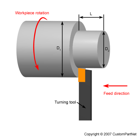
Step Turning

Step turning creates two surfaces with an abrupt change in diameters between them. The final feature resembles a step.


taper.png

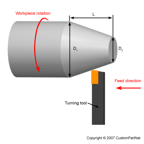
Taper Turning

Taper turning produces a ramp transition between the two surfaces with different diameters due to the angled motion between the workpiece and a cutting tool.


cham.png

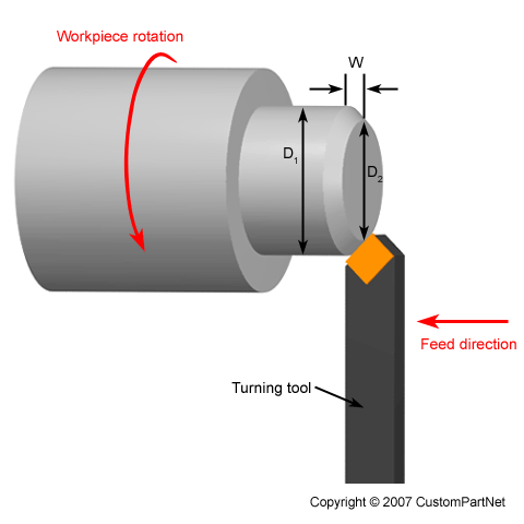
Chamfer Turning

Similar to the step turning, chamfer turning creates angled transition of an otherwise square edge between two surfaces with different turned diameters.


cont.png

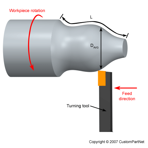
Contour Turning

In contour turning operation, the cutting tool axially follows the path with a predefined geometry. Multiple passes of a contouring tool are necessary to create desired contours in the workpiece. However, form tools can produce the same contour shape is a single pass.


2. Facing

facing.png

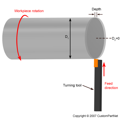
During the machining, the length of the workpieces is slightly longer than the final part should be. Facing is an operation of machining the end of a workpiece that is perpendicular to the rotating axis. During the facing, the tool moves along the radius of the workpiece to produce the desired part length and a smooth face surface by removing a thin layer of material.


3. Grooving

groov.png

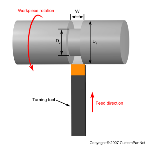
Grooving is a turning operation that creates a narrow cut, a "groove" in the workpiece. The size of the cut depends on the width of a cutting tool. Multiple tool passes are necessary to machine wider grooves. There are two types of grooving operations, external and face grooving. In external grooving, a tool moves radially into the side of the workpiece and removes the material along the cutting direction. In face grooving, the tool machines groove in the face of the workpiece. 

4. Parting 

part.png

Parting is a machining operation that results in a part cut-off at the end of the machining cycle. The process uses a tool with a specific shape to enter the workpiece perpendicular to the rotating axis and make a progressive cut while the workpiece rotates. After the edge of the cutting tool reaches the centre of the workpiece, the workpiece drops off. A part catcher is often used to catch the removed part. 

5. Threading

thread.png

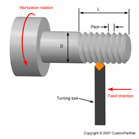
Threading is a turning operation in which a tool moves along the side of the workpiece, cutting threads in the outer surface. A thread is a uniform helical groove of specified length and pitch. Deeper threads need multiple passes of a tool.

9f75e291df15b1cc66a69bb97c417c8f.jpg

6. Knurling

Knurling operation produces serrated patterns on the surface of a part. Knurling increases the gripping friction and the visual outlook of the machined part. This machining process utilizes a unique tool that consists of a single or multiple cylindrical wheels (knurls) which can rotate inside the tool holders. The knurls contain teeth that are rolled against the surface of the workpiece to form serrated patterns. The most common knurling pastern is a diamond pattern.

drill.png

7. Drilling

Drilling operation removes the material from the inside of a workpiece. The result of drilling is a hole with a diameter equal to the size of the utilized drill bit. Drill bits are usually positioned either on a tailstock or a lathe tool holder.

8. Reaming

ream.png

Reaming is a sizing operation that enlarges the hole in the workpiece. In reaming operations, reamer enters the workpiece axially through the end and expands an existing hole to the diameter of the tool. Reaming removes a minimal amount of material and is often performed after drilling to obtain both a more accurate diameter and a smoother internal finish.

boring.png

9. Boring

In boring operation, a tool enters the workpiece axially and removes material along the internal surface to either create different shapes or to enlarge an existing hole.

tap.png

10. Tapping

Tapping is the process in which a tapping tool enters the workpiece axially and cuts the threads into an existing hole. The hole matches a corresponding bit size that can accommodate the desired tapping tool. Tapping is also the operation used to make a thread on nuts.


Conclusion

Lathes are capable of machining pieces with sophisticated features. The final part features are produced by the utilization of various tools and by changing the kinematical relationship between the cutter and a workpiece. In this article, we explained ten different lathe operations. 

We at Turntech Precision provide the top quality parts machined on the Swiss-type lathes utilizing turning, facing, grooving, threading, knurling, boring, and tapping operations. We work closely with our customers to provide them with the best solution to their engineering problems in a variety of industries. Contact us today with your inquiries.

Chip off the old block: How to control the chaos that is “chip formation”

chip-10.png

With the advent of advanced factory automation and Industry 4.0, the autonomous manufacturing systems are gaining in importance. Proper chip disposal is an essential enabler of truly autonomous machining. Read on to find out about factors affecting chip formation and techniques for their control.

In recent decades machine tools kept on continuously improving, and the autonomous machining systems established themselves as irreplaceable components of factory automation. The machining process problems, such as chip disposal, stand in the way of efficient autonomous machining systems. Therefore, effective chip control is a crucial feature of all modern machining systems.

The characteristics of formed chips depend on the type of machining material, ductile or brittle. On the other hand, machining process parameters also play an important role in the chip formation, namely, feed rate, rake angle, cutting speed, depth of cut, and friction forces (use of lubricants and coolants).

Machine operators generally tune the process parameters to obtain high-quality parts and efficient machine operation, while relaying on the chip breakers to help them with chip disposal.   


Formation of Chips

During the machining, as the tool advances into the workpiece, the metal in front of it compresses. When compression exceeds the compression limit, the metal separates from the workpiece and flows plastically in the form of a chip (shear deformation).

tec_turning_chip_control_01_en.png

The flow of metal happens at the shear plane due to the primary shear. The shear plane extends at an angle upwards from the uncut surface in front of the tool. The value of the shear angle depends on the type of material and the cutting conditions (tool angle, cutting speed, etc.). When the shear angle is small, the path of shear will be long, chips will be thick, and the cutting force will be high, and vice versa. 

As the chip slides along the face of the tooltip, the secondary shear occurs due to the friction. The friction increases the temperature of the machining process, causing the chips to heat up excessively. 


Types of Chips

The types of chips formed during the machining of metals are;

  • Segmented chips

  • Continuous chips

  • Continuous chips with the built-up edge (BUE)

Segmented (Discontinuous) Chips

original.png

Segmented chips usually occur when machining brittle metals such as brass, bronze, or cast iron. In general, the segmented chips are the result of the following machining conditions;

  • Low feed rate;

  • Low rake angle;

  • High cutting speed;

  • High tool-chip friction;

  • Significant depth of cut.

The segmented chips provide clean surface finish in brittle metals, easy chip disposal, longer tool life, and reduced power consumption. In the case of ductile metals, the segmented chips usually result in poor surface finish and lower tool life.

Continuous Chips

unnamed (1).jpg

Continous chips usually occur during the machining of malleable metals such as steel, copper, or aluminium at high cutting speeds. During the machining, the temperature between the tooltip and ductile workpiece gets high. Each layer of the removed metal gets welded to the previous layer, forming a long and continuous chip stream. In general, the continuous chips occur under the following machining conditions;

  • Small depth of cut;

  • Large rake angle;

  • High cutting speed;

  • Low tool-chip friction (use of lubricants or coolants);

  • Sharp cutting edge.

The continuous chips provide clean surface finish, longer tool life, and reduced power consumption. On the other hand, the disposal of this type of chips is challenging. It is necessary to use chip breakers to improve disposal conditions.  

Continuous Chips With the Built-Up Edge (BUE)

Different-chip-formation-mechanisms-generated-from-PM2000-specimen-machined-at-same_Q640.jpg

The formation of continuous chips with the BUE is caused by high friction between the tool and the chip while machining ductile metals. Under these conditions, some chip particles tend to bond to the tooltip. As bonded material forms the new cutting edge, it continues to build up until it breaks off from the tooltip. During the breakoff, the built-up material bonds both to the chip and the workpiece surface, resulting in poor surface finish. A different name for the formation of BUE is "chip welding." In general, continuous chips with BUE occur under the following conditions:

  • Low rake angle;

  • Low cutting speed;

  • High friction forces;

  • High feed.

Since continuous chips with BUE poorly affect the tool life, increase the power consumption, and cause the poor surface finish, their prevention is crucial. Measures such as reducing friction through the use of lubricants, preventing metal-to-metal contact through tool coatings, and reducing the temperature through the use of coolants, have a positive effect on the prevention of chip welding. 


Chip Control

Features of a Turning Insert

Features of a Turning Insert

Machining of malleable metals such as steel at high cutting speed and large rake angles leads to the formation of long and stringy chips. These sharp-edged, hot, and continuous chips that come out at high speed can endanger the safety of machine operators, damage the product by entangling with the tool and make their disposal complicated. It is imperative to break chips into manageable geometry.

Chips can break off either by self-breaking or by forced breaking. When machining ductile materials, due to the temperature and flow velocity difference, the chips tend to curl. The curled chips can self-break in three different ways:

  • By natural fracturing due to the cooling-induced strain;

  • By striking against the workpiece;

  • By striking against the tool.

The most common method for forced breaking is the use of a chip breaker.

Chip Breakers

Chipbreaker of insert with different coating and substrate

Chipbreaker of insert with different coating and substrate

The most basic function of chip breakers is to force chips to curl more tightly than they naturally would. Forced curling causes the chip to break off by striking either against the workpiece or the tool. Chip breakers improve machining efficiency by enhancing chip control and reducing cutting forces.

Most modern chip breakers come in the form of grooves or obstructions on the cutting tool. The design of chip breakers revolves around finding the best geometry for a given machining scenario, which will create the stress in the chip and cause it to break off easily.

Groove type chip breakers incorporate a small groove behind the leading cutting edge. The geometry of the curve determines the radius of the chip curvature.

Obstruction type chip breaker features distinctive geometry that resembles a step. The obstruction can be either integral or attached to the cutting tool. In the case of the "attached" type, it is possible to adjust them for various machining conditions.


Conclusion

The machining process is a subtle interplay of physics, material science, and mechatronics. During the machining, material removal is a result of interaction forces between the workpiece and the machining tool. The nature of these interaction forces defines the colour and the size of chips. The chips are valuable research and diagnostic data for cutting engineers. Nevertheless, when not handled properly, chips tend to decrease the productivity of machines.

P1120792.jpg

Three distinctive types of chips can occur during the machining, segmented, continuous, and continuous with BUE. The formation of chips depends on the material selection and machining process parameters.

Chip disposal is a vital factor to consider when improving overall machining efficiency and planning for the autonomous operation of the machines. Even though the segmented chips and continuous chips are self-breaking under certain machining conditions, it is a rule of thumb to use chip breakers in machining setups.

Breaking of the chips into suitable lengths by a chip breaker prevents the chip entanglement with the tool, decreases the vibration, and prevents the tool damage. Chip breaker also reduces the cutting resistance, which in turn prevents chipping and fracturing of the cutting edge. 

When using a chip breaker, it is necessary to choose the right one for the job. For turning operations such as finishing, medium, and roughing, we have to choose correct chip breakers for each. It is essential to use a suitable chip breaker based on the desired depth of cut, feed rate, spindle speed, and the desired surface finish.

We at Turntech Precision leverage our knowledge and experience to deliver the best and the most cost-effective Swiss-type lathe machined parts to our customers. We continually strive towards increasing efficiencies of our machines by analysing material properties, utilising advanced tooling and chip breakers, and tuning process parameters. Contact us today with your inquiries.