With the advent of advanced factory automation and Industry 4.0, the autonomous manufacturing systems are gaining in importance. Proper chip disposal is an essential enabler of truly autonomous machining. Read on to find out about factors affecting chip formation and techniques for their control.
In recent decades machine tools kept on continuously improving, and the autonomous machining systems established themselves as irreplaceable components of factory automation. The machining process problems, such as chip disposal, stand in the way of efficient autonomous machining systems. Therefore, effective chip control is a crucial feature of all modern machining systems.
The characteristics of formed chips depend on the type of machining material, ductile or brittle. On the other hand, machining process parameters also play an important role in the chip formation, namely, feed rate, rake angle, cutting speed, depth of cut, and friction forces (use of lubricants and coolants).
Machine operators generally tune the process parameters to obtain high-quality parts and efficient machine operation, while relaying on the chip breakers to help them with chip disposal.
Formation of Chips
During the machining, as the tool advances into the workpiece, the metal in front of it compresses. When compression exceeds the compression limit, the metal separates from the workpiece and flows plastically in the form of a chip (shear deformation).

The flow of metal happens at the shear plane due to the primary shear. The shear plane extends at an angle upwards from the uncut surface in front of the tool. The value of the shear angle depends on the type of material and the cutting conditions (tool angle, cutting speed, etc.). When the shear angle is small, the path of shear will be long, chips will be thick, and the cutting force will be high, and vice versa.
As the chip slides along the face of the tooltip, the secondary shear occurs due to the friction. The friction increases the temperature of the machining process, causing the chips to heat up excessively.
Types of Chips
The types of chips formed during the machining of metals are;
Segmented chips
Continuous chips
Continuous chips with the built-up edge (BUE)
Segmented (Discontinuous) Chips

Segmented chips usually occur when machining brittle metals such as brass, bronze, or cast iron. In general, the segmented chips are the result of the following machining conditions;
Low feed rate;
Low rake angle;
High cutting speed;
High tool-chip friction;
Significant depth of cut.
The segmented chips provide clean surface finish in brittle metals, easy chip disposal, longer tool life, and reduced power consumption. In the case of ductile metals, the segmented chips usually result in poor surface finish and lower tool life.
Continuous Chips

Continous chips usually occur during the machining of malleable metals such as steel, copper, or aluminium at high cutting speeds. During the machining, the temperature between the tooltip and ductile workpiece gets high. Each layer of the removed metal gets welded to the previous layer, forming a long and continuous chip stream. In general, the continuous chips occur under the following machining conditions;
Small depth of cut;
Large rake angle;
High cutting speed;
Low tool-chip friction (use of lubricants or coolants);
Sharp cutting edge.
The continuous chips provide clean surface finish, longer tool life, and reduced power consumption. On the other hand, the disposal of this type of chips is challenging. It is necessary to use chip breakers to improve disposal conditions.
Continuous Chips With the Built-Up Edge (BUE)

The formation of continuous chips with the BUE is caused by high friction between the tool and the chip while machining ductile metals. Under these conditions, some chip particles tend to bond to the tooltip. As bonded material forms the new cutting edge, it continues to build up until it breaks off from the tooltip. During the breakoff, the built-up material bonds both to the chip and the workpiece surface, resulting in poor surface finish. A different name for the formation of BUE is "chip welding." In general, continuous chips with BUE occur under the following conditions:
Low rake angle;
Low cutting speed;
High friction forces;
High feed.
Since continuous chips with BUE poorly affect the tool life, increase the power consumption, and cause the poor surface finish, their prevention is crucial. Measures such as reducing friction through the use of lubricants, preventing metal-to-metal contact through tool coatings, and reducing the temperature through the use of coolants, have a positive effect on the prevention of chip welding.
Chip Control

Features of a Turning Insert
Machining of malleable metals such as steel at high cutting speed and large rake angles leads to the formation of long and stringy chips. These sharp-edged, hot, and continuous chips that come out at high speed can endanger the safety of machine operators, damage the product by entangling with the tool and make their disposal complicated. It is imperative to break chips into manageable geometry.
Chips can break off either by self-breaking or by forced breaking. When machining ductile materials, due to the temperature and flow velocity difference, the chips tend to curl. The curled chips can self-break in three different ways:
By natural fracturing due to the cooling-induced strain;
By striking against the workpiece;
By striking against the tool.
The most common method for forced breaking is the use of a chip breaker.
Chip Breakers
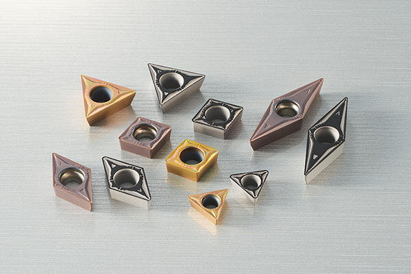
Chipbreaker of insert with different coating and substrate
The most basic function of chip breakers is to force chips to curl more tightly than they naturally would. Forced curling causes the chip to break off by striking either against the workpiece or the tool. Chip breakers improve machining efficiency by enhancing chip control and reducing cutting forces.
Most modern chip breakers come in the form of grooves or obstructions on the cutting tool. The design of chip breakers revolves around finding the best geometry for a given machining scenario, which will create the stress in the chip and cause it to break off easily.
Groove type chip breakers incorporate a small groove behind the leading cutting edge. The geometry of the curve determines the radius of the chip curvature.
Obstruction type chip breaker features distinctive geometry that resembles a step. The obstruction can be either integral or attached to the cutting tool. In the case of the "attached" type, it is possible to adjust them for various machining conditions.
Conclusion
The machining process is a subtle interplay of physics, material science, and mechatronics. During the machining, material removal is a result of interaction forces between the workpiece and the machining tool. The nature of these interaction forces defines the colour and the size of chips. The chips are valuable research and diagnostic data for cutting engineers. Nevertheless, when not handled properly, chips tend to decrease the productivity of machines.

Three distinctive types of chips can occur during the machining, segmented, continuous, and continuous with BUE. The formation of chips depends on the material selection and machining process parameters.
Chip disposal is a vital factor to consider when improving overall machining efficiency and planning for the autonomous operation of the machines. Even though the segmented chips and continuous chips are self-breaking under certain machining conditions, it is a rule of thumb to use chip breakers in machining setups.
Breaking of the chips into suitable lengths by a chip breaker prevents the chip entanglement with the tool, decreases the vibration, and prevents the tool damage. Chip breaker also reduces the cutting resistance, which in turn prevents chipping and fracturing of the cutting edge.
When using a chip breaker, it is necessary to choose the right one for the job. For turning operations such as finishing, medium, and roughing, we have to choose correct chip breakers for each. It is essential to use a suitable chip breaker based on the desired depth of cut, feed rate, spindle speed, and the desired surface finish.
We at Turntech Precision leverage our knowledge and experience to deliver the best and the most cost-effective Swiss-type lathe machined parts to our customers. We continually strive towards increasing efficiencies of our machines by analysing material properties, utilising advanced tooling and chip breakers, and tuning process parameters. Contact us today with your inquiries.